Edge Detector Circuit Diagram
Edge detector circuit Circuit detector cis detection Timing detector
Edge Detector Circuit Diagram
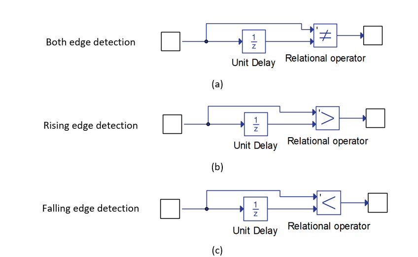
Log edge detection Circuit schematic for the edge detector element. the shaded regions Edge-triggered latches: flip-flops
Falling and rasing edge detector
Edge detector falling pulse circuit rasing here input sending constant alternating output electrical stack slightly delay rc examples three whichDetector vhdl figure2 implementation typical Dld lecture-1: edge detector circuit (explained in bangla)Detector circuit.
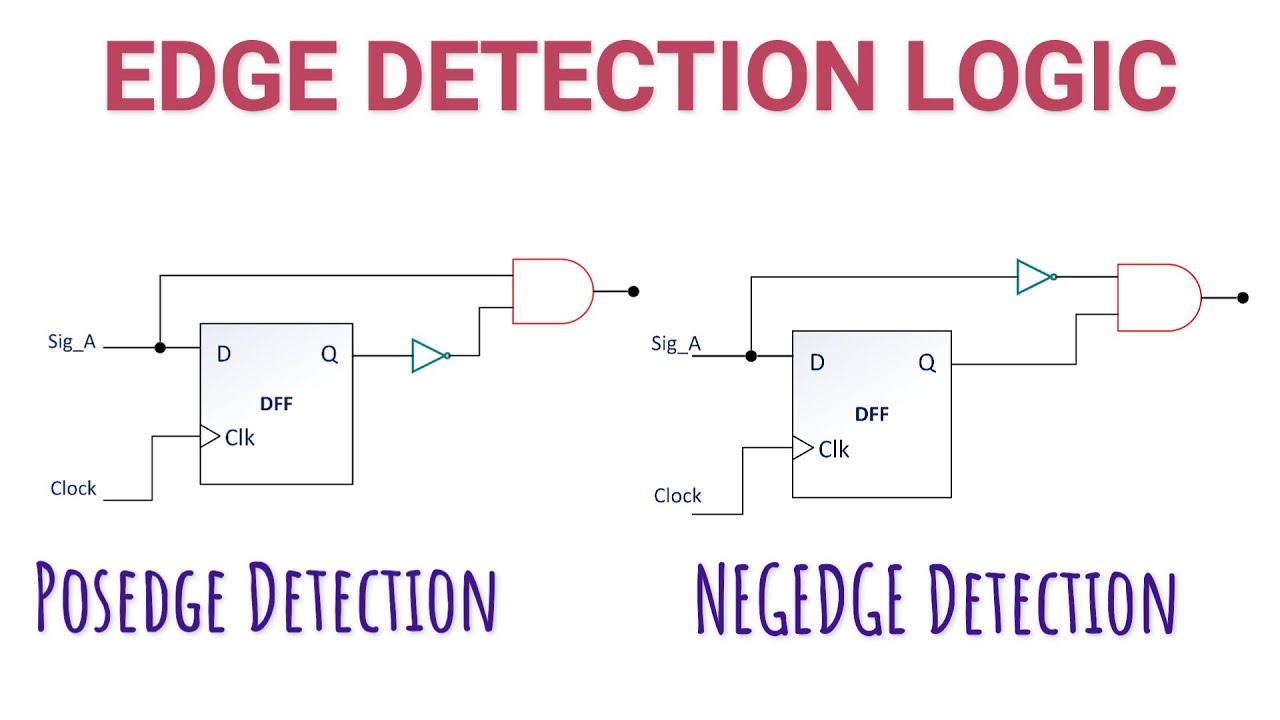
Edge detector circuit diagramPositive and negative edge detector Rising and falling edge detectorsElectronic – dual edge detector – valuable tech notes.

Edge detector rising capacitor using resistor schematic circuit does why work circuitlab created
Edge logic triggering simple trigger detector pulse width inputDetector triggered circuit latches flops nor Detector shaded regionsEdge detection.
Sensor circuit page 2 : sensors detectors circuits :: next.grWhy does this rising edge detector using a capacitor and a resistor Big > demo > subpixel edge detectionHow to create an asynchronous edge detector in vhdl?.

Edge-triggering on simple logic
Saving energy: discrete edge detector for driving latching relaysSolved the dual edge detector circuit shown in figure 3.3 Conversion of single optical encoder to dual encoder using digitalDigital design.
Edge detector dual vhdl asynchronous code output create quartus intel altera ii stackDetection rising falling component output edges hil typhoon Edge detector circuit diagramFalling and rasing edge detector.

Circuit detector encoder optical
Edge detector falling rasing usingSn74lvc1g123: rising/falling edge detector reliability problem Edge detector circuit falling rising flipflops delay to1 useNi myrio: detect a switch transition.
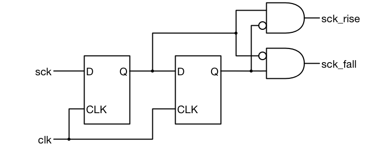
Edge detector circuit verilog positive detect negative digital circuits code beyond pos neg i2s clk diagram advise expert below sckLatching relays detector edge saving discrete driving energy relay schematics Edge detector dual power using xor glitch low circuit too much gate converter made stack[solved] edge detection circuit (opamps).

Circuit design
(a) timing diagram and (b) circuit of the edge detector.Edge detector canny demo classical detection projects epfl ch (a) timing diagram and (b) circuit of the edge detector.Edge detection circuit diagram.
Edge detector rising falling circuit reliability problem ti e2e make improvement question any there logicDetector edge circuit hackaday io log video How to design a good edge detectorEdge detector circuit dual rising transistor input xor transition logic exor schmitt trigger gives power clk falling down gate output.
Opamps kicad 1116
Transistor diagram of edge detector used with clock.Edge circuit pulse positive input sensor negative going output short detector circuits gr next capacitor waveform provides every .
.


Falling and Rasing Edge Detector - Electrical Engineering Stack Exchange

How to design a good Edge Detector - Surf-VHDL
Edge Detection Circuit Diagram

Why does this rising edge detector using a capacitor and a resistor
Digital Design - Expert Advise : Pos n Neg edge detector

Edge Detector Circuit Diagram